Matrix Phase II
The addressing and multiplexing for the Adafruit display, which I mimicked, is referred to as a 1-in-8 refresh, that is 1 out of 8 rows is refreshed at a time. Because 16 rows now had to be refreshed, row 1 is activated along with row 9, row 2 with row 10, etc. In other words, rows 1-8 are parallel connected (electrically) with rows 9-16. For the extra boards required to drive the next 8 rows, I used the same PCB layout as I did for the main logic board (the one with MCU on it), but stripped it down to bare minimum with only DM13 latches and 74540 buffer chips. No power supply, and no row decoder because they were not needed.
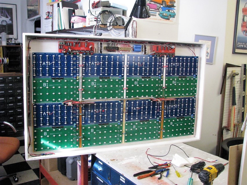
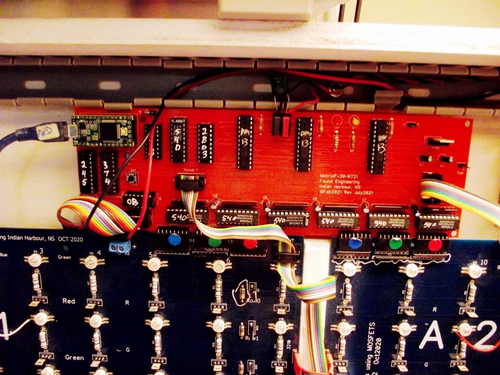
The only issue I had was how to install these boards. If I laid them flat, they would cover the bottom row of pixels of the board above it. If I put them on a level UNDER the pixel board, it would be impossible to troubleshoot. So I stood them up perpendicular to the board they plugged into. They can be seen in photo at top right, between rows 8 and 9. (Later, I moved them down under the top pixel boards, since I've never HAD to troubleshoot them.)
Tuesday, July 27, 2021
At first I thought this would be the easy part, just duplicate Part 1, but with only ONE MCU to control the whole thing, how could this be done?The addressing and multiplexing for the Adafruit display, which I mimicked, is referred to as a 1-in-8 refresh, that is 1 out of 8 rows is refreshed at a time. Because 16 rows now had to be refreshed, row 1 is activated along with row 9, row 2 with row 10, etc. In other words, rows 1-8 are parallel connected (electrically) with rows 9-16. For the extra boards required to drive the next 8 rows, I used the same PCB layout as I did for the main logic board (the one with MCU on it), but stripped it down to bare minimum with only DM13 latches and 74540 buffer chips. No power supply, and no row decoder because they were not needed.
The only issue I had was how to install these boards. If I laid them flat, they would cover the bottom row of pixels of the board above it. If I put them on a level UNDER the pixel board, it would be impossible to troubleshoot. So I stood them up perpendicular to the board they plugged into. They can be seen in photo at top right, between rows 8 and 9. (Later, I moved them down under the top pixel boards, since I've never HAD to troubleshoot them.)
Send Comments
New MCU
Biggest issue? O/P of Teensy is 3.3 volts, not the logic 5 volts I was getting with the Atmega, so I would need level shifters. I made a couple dongles with the required logic and drivers and after proving they worked, I re-made the MPU board using ONLY the Teensy (not Atmega), but with the level shifting logic. This was MPU board #4.
I purchased a board made by PixelMatix that is used with a Teensy and the Adafruit Matrix Panel, and mimicked it for the logic. I liked the idea of using flip-flops (74HC374) to determine when to write to the rows.
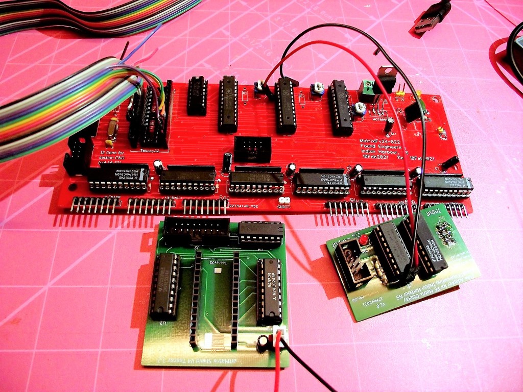
In the photo above, the two green PCBs are "dongles", used with "old" logic board to test the system. After confirming it worked, I merged the two green boards with the red one to make the FINAL PCB (below).
Wednesday, September 22, 2021
I was able to get some semblance of a display using the Atmega 328, an 8 bit device, but there were color issues, and some random light twinkling. I had anticipated this but didn't plan very well for it when I made my last MCU board with ability to swap in a 32 bit Teensy V3.2 MCU for the Atmega MCU. The idea was sound but my random selection of digital pins was bad and a simple swap just did NOT work.Biggest issue? O/P of Teensy is 3.3 volts, not the logic 5 volts I was getting with the Atmega, so I would need level shifters. I made a couple dongles with the required logic and drivers and after proving they worked, I re-made the MPU board using ONLY the Teensy (not Atmega), but with the level shifting logic. This was MPU board #4.
I purchased a board made by PixelMatix that is used with a Teensy and the Adafruit Matrix Panel, and mimicked it for the logic. I liked the idea of using flip-flops (74HC374) to determine when to write to the rows.
In the photo above, the two green PCBs are "dongles", used with "old" logic board to test the system. After confirming it worked, I merged the two green boards with the red one to make the FINAL PCB (below).

Teensy is at above left. I wrote on the chips with white paint to readily identify them during troubleshooting. Surprisingly, the board worked the first time with no problems at all. This NEVER happens.
Prorgamming
So, I just hard-coded it, using Excel to map image points to matrix x,y points.
Sunday, September 26, 2021
My main focus and reason for making the matrix display was to display our national and provincial flags. When others put out cloth flags on special days, I can show the electronic version. I tried grabbing a GIF or JPG of a flag and converting to BMP for display using an MCU, but the algorithm made the edges fuzzy. This of course had to do with squeezing the image down to 16x32 pixels: not exactly high res.So, I just hard-coded it, using Excel to map image points to matrix x,y points.

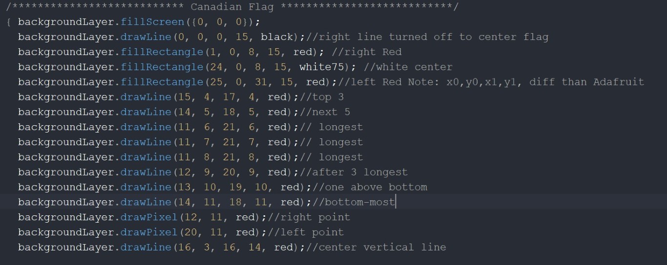
Then I used the functions provided in SmartMatrix software library to display the blocks, lines or pixels (below). I had created this on my 8x32 display using Adafruit software library, but when I upgraded to the 16x32, necessitating the Teensy MPU over the UNO (Atmega 328), I changed libraries.
Copyright 2022 Queenidog - All Rights Reserved